Affiliate Disclosure: This post may include affiliate links. If you click and make a purchase, I may earn a small commission at no extra cost to you.
Flash Drives store the data with the help of NAND flash memory. This is a non-volatile memory that operates with the help of floating gate transistors which are also called memory cells. These tiny cells store the data in the form of electric charge to represent the bits. A controller handles all the tasks related to reading, writing, wear-leveling, and correction of bad data. The drive connects to the computer through the USB ports and gets all the required power from there.
The connection is established and controlled by the chipset on the motherboard on the host side. However, inside the drive, all the processing tasks are done by the controller. So, if you want to understand how a flash drive works, you first learn what is the NAND flash memory and how it works. Also, it is important to know a little about the interface and the host interaction. Let’s discuss all these things in this article.
Physical Components of a Flash Drive
The two key physical components of a flash drive are the controller and the NAND flash memory chip. The controller handles the data read and write request from the system and the NAND flash memory is where the data is stored.

Along with these, there will be a PCB on which all the components are soldered. The connection is established through a USB connector. There is also a crystal oscillator that produces the device’s main clock. Some other components like resistors and capacitors are there. All these things are then enclosed inside a plastic or metallic casing.
The Storage Medium: Flash Memory
Inside a flash drive, the NAND flash memory is used to store the data. In a single memory chip, there could be millions of nanoscopic floating-gate or charge-trap flash cells. The modern 3D NAND technology primarily utilizes charge trap flash. Each of these transistors makes a single memory cell. Each cell can be used to hold multiple bits of data (discussed in the next section). Each cell has the data in the form of an electric charge.

The charge is inserted inside these cells during the writing process by the controller. A high voltage is passed through the transistor, resulting in a significant charge disturbance. Some of the excited charges pass the insulating layer (covering the floating gate) and enter the floating gate. The amount of applied voltage depends on the incoming data and bit values. If a transistor needs to be charged at 100%, the passing voltage will be higher compared to when it is charged at 0%.
Once the charge is stored inside the floating gate transistor, it will stay there even if the flash drive is disconnected from your computer. If the controller has to read the same data, the threshold voltage of that cell is checked to determine its bit values. You can learn more about the threshold voltage and the detailed reading and writing process in this article. The threshold voltage of the transistor changes depending on the level of charge in the floating gate. This change in the threshold voltage is used to read the data.
Floating gate transistor as a memory cell
The basic concept of a floating gate transistor is that it has a separate layer called a floating gate, and this gate is insulated by a special material. There is an insulation layer around this floating gate that stops the charge from leaking out. In SLC SSDs, the presence of this charge is represented by bit 0, and its absence is represented by bit 1. Other types of memory cells are discussed below.
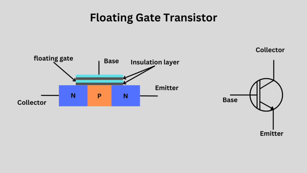
The normal transistor works just as a switch or amplifier. However, due to its unique characteristics, the floating gate or charge-trap cell is an ideal candidate for long-term charge storage. The engineer utilizes this long-term charge storage to make long-term memory. For a transistor, the charge is just a charge, but we have programmed our controllers and computers to interpret it as bits, thereby generating valid data.
Types of Flash Memory
There are four types of flash memory cells based on the amount of data they can store. These are SLC, MLC, TLC, and QLC.
In SLC (Single-Level Cell) NAND flash memory, each floating gate transistor or memory cell stores just one bit of value. It means there are just two possible positions of a cell i.e. high or low. SLC NAND flash is pretty expensive and used mainly in enterprise environments. You will not be able to find a flash drive with SLC memory.
In MLC (Multi-Level Cell) NAND flash memory, each floating gate transistor or memory cell is now storing two bits. This happens by dividing the two voltage levels, i.e., high and low, into four different voltage levels. This makes 4 possible voltage levels inside a single cell. This increases the storage density at the cost of performance and endurance. Again, MLC NAND flash is mostly reserved for enterprise SSDs and you will hardly find a flash drive with MLC NAND flash.
In TLC (Triple-Level Cell), each cell is now capable of storing 3 bits of data. This is done by creating up to 8 different voltage levels in each cell. The storage density is increased a lot, but the performance and endurance are compromised more. You will find the TLC NAND flash in most of the high-end flash drives. These drives give the value for money in terms of read/write performance.
In QLC (Quad-Level Cell), each memory cell is now holding 4 bits of data. Now, the total possible voltage levels are 16. Therefore, storage density is further increased. Most budget flash drives will come with the QLC NAND flash, which is considered to be the least reliable of these four. However, because flash drives aren’t intended for long-term critical data storage, QLC offers the best value for money to buyers.
Interaction with the host system
When you connect your flash drive to your computer through the USB port, the computer recognizes this drive through the USB interface. The required power is supplied to ensure the drive is correctly connected to the system. After this, device enumeration begins, which primarily involves obtaining information about the drive, including the supported file system, capacity, and device type. After this, the operating system looks for the driver and assigns it to the drive. If the USB driver isn’t updated, the system may not work with the drive or may not allow it to operate at its highest speed.
With the help of a driver, the operating system mounts the flash drive and assigns it a drive letter, such as “D: or E:”. Now, your drive is accessible through the file system.
To understand the data on the drive, the OS reads its partition tables and file allocation tables. Once the operating system has all the information about the drive and the connection is established, the users are allowed to utilize the drive for any type of data storage.
The operating systems also require you to “Eject” the drive before removing it from the port. You will find this option in your drive on all operating systems. This ensures that all pending read/write operations are completed correctly and that all data is saved to your drive.
Although many steps and numerous small things are happening, this takes just a second or so. Your drives are generally available for use immediately after plugging in.
Storage of Data: Storing 0’s and 1’s
For this explanation, I am using the example of TLC NAND flash. We suppose our flash drive has the flash memory that uses a single cell to hold 3 bits of data.

When a cell has a 0% charge level, the controller considers it as a “0 0 0” bit value and “1 1 1” when it is 100% charged. Now, if I have to store these bits (0 0 0 1 0 1 1 1 1) which represent some data, the controller would take three TLC cells and charge them at the voltage levels that represent those bit values.
For “0 0 0, the controller would discharge the first cell completely.
For the next “1 0 1” values, the cell would be charged near around 75%.
And for the last value “1 1 1“, the third TLC cell would be charged hundred percent.
The controller would store the information about the location of data inside the NAND flash because most flash drives don’t come with DRAM. So, the FTL (Flash Transition Layer) is stored on a specific part of the main memory chip.
The computer sends the data in the form of 0s and 1s to the pen drive. The controller just assigns these bits as they come to the NAND flash memory. It then remembers the location and saves it on the flash itself. The flow of the incoming and outgoing data is always going to be in the form of bits. The USB controller on the device handles the conversion of these bits into data blocks that are stored or retrieved from the NAND flash memory.
Blocks and Pages
Just like SSDs, flash drives don’t write directly to the cells. These read/write operations are done on broader levels. The cells are combined into pages and blocks. A page is the smallest readable and writable unit in NAND flash. While the block is the smallest erasable unit. So, if we have to write any amount of data, a whole page (usually 4KB in size) will be utilized. The same goes for erasing the data. If some data has to be erased, the whole block containing that data would be erased. However, the controller first moves the valid data to a separate location before the deletion.
Blocks and Pages are used to increase the performance in NAND flash and also to reduce errors. If the controller has to read, write, or erase the cells, it would take a lot longer to locate the cells. Additionally, when charging the cells or checking their voltages, the likelihood of errors in nearby cells increases.
The Controller
The key functions of a controller are data management, error correction, garbage collection, bad-block management, and handling the Flash Transition layer. The most popular controller manufacturers for flash drives are Phison, Marvell, and Silicon Motion. The selection of a controller depends on the size, price, and type of the flash drive. The high-end controllers that come with expensive drives come with simultaneous read/write functionality and advanced algorithm support. The low-end controllers are basic ones that normally just read and write data or do only the essential things.
The main function of the controller is to handle the conversation between the main system and the flash memory. For both reading and writing the data, the request from the host system goes through the controller. Another key role of the controller is to run the wear-leveling algorithms that distribute the data across the NAND flash memory. Wear leveling makes sure that no specific cells are used over and over again for data storage and are worn down faster than the other ones.
Garbage collection, which is the process of consolidating the free space by removing the invalid data, is also run by the controller.
With the help of the Flash transition layer, the controller is responsible for converting the logical block addresses coming from the computer to the physical addresses on the NAND flash memory. Therefore, the controller has many tasks to handle, which generally require some processing power. All the algorithms are handled by the controller along with the incoming flow of data.
The Interface
The interface in flash drives decides the method by which it would interact and connect with the host system. Most flash drives use the USB (Universal Serial Bus) interface to establish connections. Your flash drive’s read/write speed will also depend on the interface. If a drive is made to work for higher performance, its supported USB interface must also be of a higher version. Although the USB interface is forward and backward-compatible on the software level, installing a faster USB drive on an older and slower USB port can result in a performance bottleneck. For physical compatibility between Type-A and Type-C, you can use the adapters available in the market.
| Interface/Version | Release Year | Connector Type | Bandwidth |
|---|---|---|---|
| USB 1.0 | 1996 | USB Type-A | 1.5 Mbps (Low-Speed) |
| USB 1.1 | 1998 | USB Type-A | 12 Mbps (Full-Speed) |
| USB 2.0 | 2000 | USB Type-A, USB Type-B | 480 Mbps (High-Speed) |
| USB 3.0 (USB 3.1 Gen 1) | 2008 | USB Type-A, USB Type-B | 5 Gbps (SuperSpeed) |
| USB 3.1 Gen 2 | 2013 | USB Type-A, USB Type-C | 10 Gbps (SuperSpeed+) |
| USB 3.2 Gen 1×1 | 2017 | USB Type-A, USB Type-C | 5 Gbps |
| USB 3.2 Gen 2×1 | 2017 | USB Type-A, USB Type-C | 10 Gbps |
| USB 3.2 Gen 2×2 | 2017 | USB Type-C | 20 Gbps |
| USB4 Gen 2×2 | 2019 | USB Type-C | 20 Gbps |
| USB4 Gen 3×2 | 2019 | USB Type-C | 40 Gbps |
| USB4 Version 2.0 | 2022 | USB Type-C | Up to 80 Gbps |
| Thunderbolt 1 | 2011 | Mini DisplayPort | 10 Gbps |
| Thunderbolt 2 | 2013 | Mini DisplayPort | 20 Gbps |
| Thunderbolt 3 | 2015 | USB Type-C | 40 Gbps |
| Thunderbolt 4 | 2020 | USB Type-C | 40 Gbps |
You will find all the USB drives using any of these interfaces. It is possible that the drive doesn’t offer the speed that the interface is designed for. But, using them on the same ports with updated drives is good for performance and compatibility.

