Affiliate Disclosure: This post may include affiliate links. If you click and make a purchase, I may earn a small commission at no extra cost to you.
Hard drives are non-volatile storage drives used in computers, laptops, data centers, external storage drives, etc. They are known for their higher data retention and cheaper prices. However, they are pretty complex and intricate storage devices. With the help of magnetism, very large storage capacities can be achieved. It is easy to find hard drives with 20TB of storage. The closest competitor of hard drives is SSDs, which I have discussed here.
Hard drives offered pretty decent performance in their time, but now they are getting almost replaced by the solid state drives as the boot drives. But, they still have many applications in both consumer and enterprise environments. Working on a drive is easy to understand on the surface level. However, in order to properly understand, you must have a good knowledge of magnetism, electronics, and mechanics. In this article, we will try to discuss how hard drives work. So, let’s get started.

Parts of a Hard Drive
1. Magnetic Platters
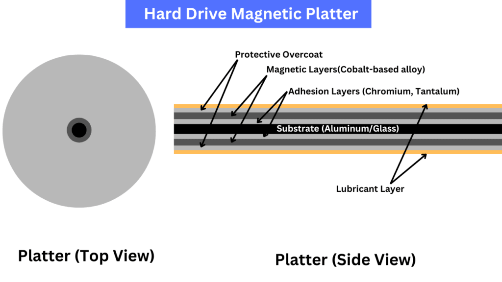
The data is stored on the magnetic platters inside the hard drives. Hard drives also have cache memory but the main storage location is the magnetic surface. The base material of the magnetic platter is either aluminum or glass. Now, because a single platter can be used on both sides for data storage, it has four main layers on both sides. The first layer over the substrate is the adhesion layer, which helps the magnetic layer adhere to the base layer. The magnetic layer is over the adhesion layer, the key data storage layer. It is covered with a cobalt-based alloy, which can be magnetized in order to represent and store bits of data. In PMR (Perpendicular Magnetic Recording) hard drives, there can be more than one magnetic layer.
The actual functional magnetic layer is around 120nm thick.
In some hard drives, such as PMR or Single magnetic recording, there could be an intermediate buffer layer after the adhesion layer to provide stability to the magnetic layer.
Normally, a protective layer will be applied over the magnetic layer. It is a diamond-like carbon layer that protects the magnetic layer from wear, moisture, oxidation, and other physical damage. The top layer on the platter is the lubricant layer made up of Perfluoropolyether (PFPE) lubricant. The role of this layer is simply to reduce the friction between the platter surface and the read/write heads.
Platter surface divisions
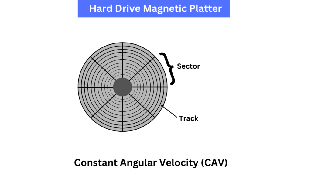
The surface of the platter is divided into multiple regions called tracks and sectors. The circular divisions are tracks while the subdivisions of each circular track are called a sector. Depending on the type of divisions, there are two types of hard drives i.e. CSV (Constant Angular Velocity) and ZBR (Zoned Bit Recording).\
In the CSV, each track (both inner and outer parts) of the platter has the same number of sectors. Now, because the sectors are evenly sized across the platter, the outer sectors store the data less efficiently because they cover more area but have the same number of sectors. The latest hard drive scan has more than 500000 tracks on each side of the platter.
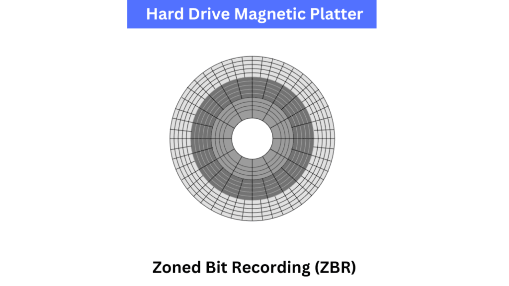
In ZBR, the number of sectors is increased as we move outwards from the center of the platter. Now, because the outer tracks have more sectors, it results in more efficient use of the platter space. Along with the efficiency, the performance and storage capacity are increased compared to the CAV because all the platter space is utilized properly. Most modern hard drives use the ZBR platter division method. Below is what a ZBR platter may look like.
The smallest read or write unit on a traditional hard drive (HDD) is a sector. The modern hard drives can have sectors of 4,096 bytes (4 KB). In older hard drives, the standard sector size was 512 bytes.
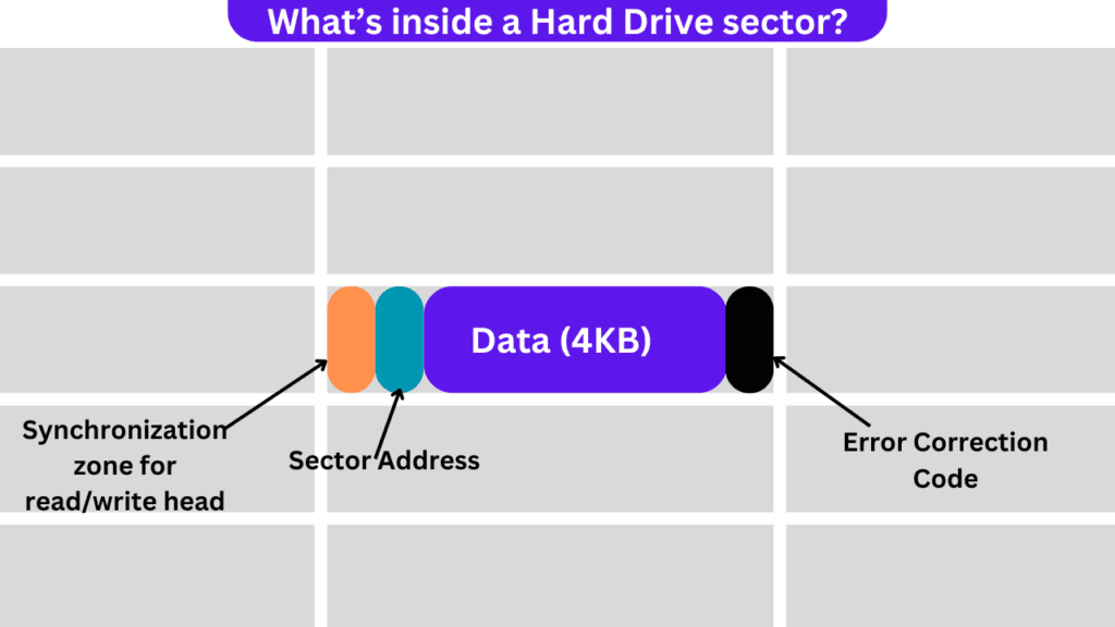
What is in a sector?
A sector would have four main parts. The first one is the pre-amble or the synchronization zone that tells the speed of the platter. The address part of the sector tells the read/write head where it is positioned on the platter. The data section of the sector covers the largest area and this is where the actual data is stored. The ECC area is used to verify whether the data stored on the block is accurately written or not. The gap between each sector allows for some tolerance while reading or writing the data.
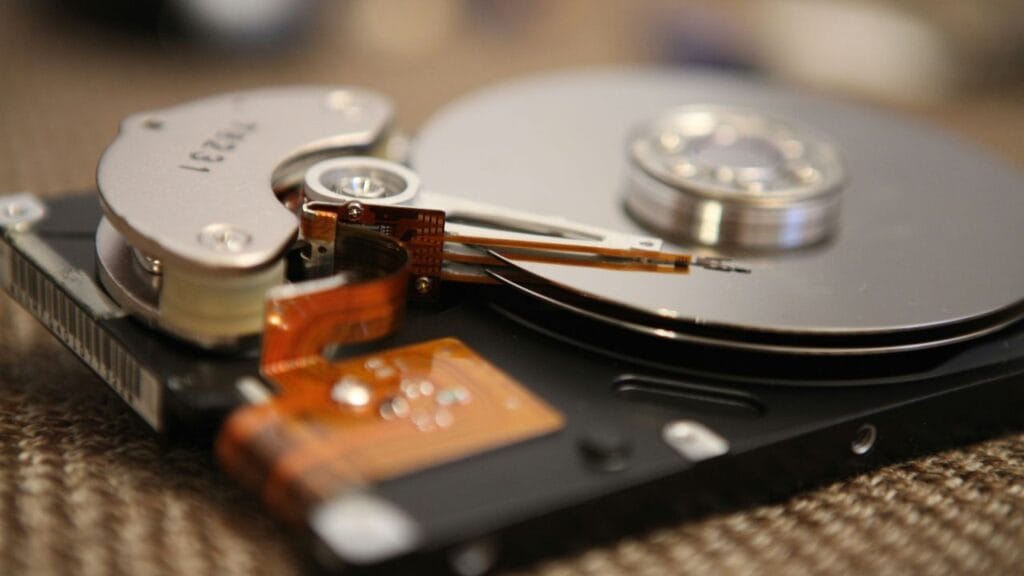
2. Read/Write Head
The metallic arm visible in the image below is the read/write head of the hard drive. As the name suggests, it reads and writes the data from and to the hard drive platter. How do they do it? We are going to discuss this a little later. The read/write head is an important part of the actuator assembly that is composed of other things like magnets and a voice coil to move the read/write head properly over the right read or write locations.
The read element on this head is magnetoresistive, which reads the data from the platter by detecting the magnetic fields. The change in magnetic polarity is sensed in order to retrieve the required data from specific sectors.
The write element generates the magnetic field in a very small coil of wire with inductive technology. When a very small electric current is passed through the write coil, it produces a magnetic field that changes the magnetic polarity of magnetic grains on the platter surface. This orientation of the magnetic field on two magnetic domains represents a bit (0 or 1) of data. The read-write head can move very fast over the surface at a distance of some nanometers.

The voice coil moves the read/write head at a very fast pace however the arm holds the read/write heads so that they can properly fly over the platter’s surface.
3. Circuitry
The main components of the hard drive circuitry are the PCB, controller, Buffer memory, data and address buses, interface controller, error correction circuitry, and firmware.
The main component of the hard drive circuitry is its controller. It interfaces with the computer’s motherboard and then the CPU through interfaces like SATA or SCSI. It handles the data read/write requests, error correction, mapping tables, etc. The actuator assembly can also be considered a part of the circuitry. It has two main components: the VCM (Voice Coil Motor) and the Arm Mount. Its main role is to move the read/write head to the specific location given by the controller. The hard drive cache is discussed in this article in detail. The address and data buses carry data between different components, such as the controller and from the buffer to the interface controller.
4. Spindle Motor
The spindle motor spins the platters at high speeds (typically 5,400 to 15,000 RPM). The speed varies depending on the specific model and the speed of the hard drive. This motor is controlled by the hard drive’s controller, depending on the task at hand. For finding random data, the read head may have to move to discrete locations, and the speed of the motor may be adjusted accordingly. However, for sequential data, the spindle motor can rotate at its full speed as well.
Hard Drive Interaction with the CPU
The hard drives use the SATA interface to connect to the CPU. The connection is typically routed through the chipset and is controlled by the AHCI transfer protocol. The SATA-3 interface is limited to a maximum bandwidth of 600 MB/s. Generally, the southbridge manages the slower peripheral buses and components, including the SATA and PATA drives. However, in some architectures, the northbridge can connect to the HDD, allowing for more bandwidth.
All modern consumer hard drives use the SATA interface for the hard drives. The maximum transfer rate with the SATA-3 version is up to 6 GB/s or 750 MB/s. However, the effective speed in the real world is up to 600 MB/s. In desktops, the SATA cables are used for data movement, while the hard drives require a separate power supply, which generally comes from the PSU’s SATA cables. In laptops, the hard drives are connected through the combined SATA 2.5″ ports. The enterprise hard drives use the SCSI interface, which offers the maximum bandwidth of up to 12GB/s per channel. The data movement is controlled by the AHCI protocol in the case of SATA hard drives.
Writing the Data to the hard drive
Write request and chipset: The first step is the initiation of the write command which is done by the CPU. The operating system then converts this write request into multiple commands and sends the write command to the hard drive typically through the chipset. Before the actual data is written, the data is temporarily written to the write buffer which is generally faster than the actual speed of the hard drive. This helps in managing the data efficiently and handling the incoming data properly. The associated data with the write command is sent from the CPU to the chipset.
Targeting the sector: The controller on the hard drive decides where the data has to be written. Each location on the drive is specified by its track and sectors. The controller finds the appropriate location depending on the type and size of the data to be written. Along with the targeting of sectors and tracks, the seek command is sent by the hard drive’s controller to the actuator assembly so that the read/write head can reach the specified location on the platter.
Writing the data: The right head is activated and it generates an electric field that changes the magnetic domains on the localized regions on the platter’s surface. The read-write head can magnetize the region in either an up or down direction. The size of each magnetic domain is in nanometers and when charged all the atoms will have their north or south poles pointing in the same direction.
To change the magnetic orientation of a domain, a magnetic field is applied by the write head. However, it isn’t that one domain orientation represents a binary 0 and the other one a binary 1. We will discuss it when we see how the data is read. For now, just understand that when the electric current is applied to the coil in the write head, it induces the magnetic field which can change the polarity of the magnetic domain on the platter’s surface.

Completion and acknowledgment: Once the write operation is finished, the controller may perform the verification process to confirm that the data is written properly. Once it is confirmed, the confirmation is also sent to the chipset, which then reaches the CPU. After the confirmation, the operating system also updates the files to reflect the changes.
Reading the Data from the hard drive
When the data read request comes from the CPU, the read/write head is sent the exact location of the sector’s starting address. The process of reading data is done by checking the magnetic fields between two magnetic domains.
We just discussed how the data is written, but when the data is read, the read head works differently. It doesn’t detect the polarity of a single magnetic domain but the change in the magnetic field. Because magnets attract opposite poles, the combined magnetic field when the opposite poles are attracted is higher than the magnetic field of the individual magnetic domains. For example, if two adjacent domains and charged oppositely when the data is written, there will be a magnetic field between those domains. This magnetic field is detected by the read head when reading the data. This image will make things clear for you.
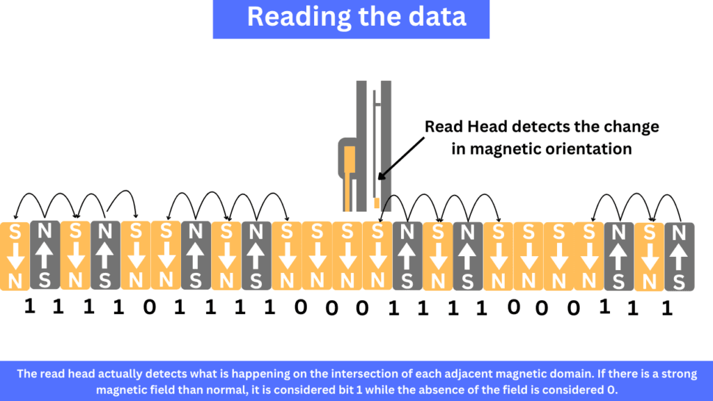
The read head is made up of a magnetoresistance material that changes its resistivity depending on the magnetic field applied to it. So, when it rides over the magnetic domains, it changes its output which can then be interpreted as the data. The preamble and the ECC in each sector help to make sure the data is read and written accurately especially when there are long series of 0s and 1s.
The read data is sent to the CPU through the data bus and the chipset. Now, if there are delays in reading the data, the system will have to wait for it which is what we call the storage bottlenecks.
CMR vs SMR Hard Drives
The two popular types of recording technologies in hard drives are CMR (Classic Magnetic Recording) and SMR (Shingled Magnetic Recording). I have discussed their work and the differences in this article.
Pros and Cons of Hard Drives in Modern Computers
Hard Drives have served a lot in earlier times, and they still offer what they are best at. Hard drives are still great for RAIDs, archival storage, and backups. They offer a good price-per-GB as compared to solid-state drives. However, there are some serious drawbacks that we face when we use hard drives with our modern systems as our main OS drives.
Because modern CPUs and RAMs are getting faster and faster, the hard drives can’t catch up with the increasing data read/write demands. Hard drives have very high latency, which can easily bottleneck our system’s performance. Slow storage drives result in longer boot and software loading times. The mechanical nature of the hard drive results in slow read/write operations, which have been overcome by the SSDs.
As we discussed above, hard drives contain mechanical and moving parts. They are prone to damage and malfunction when exposed to physical shocks and vibrations. Over time, these mechanical parts experience wear and tear, unlike solid-state drives. Also, the noise levels are higher than the SSDs.
Along with that, hard drives have fragmentation issues, higher power consumption, data recovery challenges, and slow read/write speeds. All these things are slowly making hard drives unsuitable as the primary boot drives. However, they still have many applications for raw data storage because of their high reliability and low prices.
I hope this helps!
Resources:
https://pages.cs.wisc.edu/~remzi/OSTEP/file-disks.pdf
https://pages.cs.wisc.edu/~remzi/OSTEP/file-disks.pdf
https://ieeexplore.ieee.org/abstract/document/5386854
https://www.sciencedirect.com/topics/physics-and-astronomy/magnetic-hard-disk